Thursday, September 19, 2019

What Is Electricity?

What Is Electricity?

Electricity is a form of energy. Electricity is the flow of electrons. All matter is made up of atoms, and an atom has a center, called a nucleus. The nucleus contains positively charged particles called protons and uncharged particles called neutrons. The nucleus of an atom is surrounded by negatively charged particles called electrons. The negative charge of an electron is equal to the positive charge of a proton, and the number of electrons in an atom is usually equal to the number of protons
When the balancing force between protons and electrons is upset by an outside force, an atom may gain or lose an electron. When electrons are "lost" from an atom, the free movement of these electrons constitutes an electric current.
Electricity is a basic part of nature and it is one of our most widely used forms of energy. We get electricity, which is a secondary energy source, from the conversion of other sources of energy, like coal, natural gas, oil, nuclear power and other natural sources, which are called primary sources. Many cities and towns were built alongside waterfalls (a primary source of mechanical energy) that turned water wheels to perform work. Before electricity generation began slightly over 100 years ago, houses were lit with kerosene lamps, food was cooled in iceboxes, and rooms were warmed by wood-burning or coal-burning stoves.
Beginning with Benjamin Franklin's experiment with a kite one stormy night in Philadelphia, the principles of electricity gradually became understood. In the mid-1800s, everyone's life changed with the invention of the electric light bulb. Prior to 1879, electricity had been used in arc lights for outdoor lighting. The lightbulb's invention used electricity to bring indoor lighting to our homes
Sunday, September 15, 2019

Magnetic fi elds and fl ux patterns and Electrical transformers

Lines of magnetic fl ux have no physical existence but were introduced by Michael Faraday as a way of
explaining the magnetic energy existing in space or in a material. The magnetic fi elds around a permanent
magnet, a current carrying conductor and a solenoid are shown in Figs 2.5, 2.6 and 2.7

Magnetism

 1. Draw in the magnetic fl ux patterns for the magnets shown below:
Electrical transformers
● A transformer is an electrical machine without moving parts, which is used to change the value of an
alternating voltage.
● A transformer will only work on an alternating supply.
● It will not normally work from a d.c. supply such as a battery.
● A transformer such as that shown below in Fig. 2.8 consists of two coils called the primary and second-
ary coils or windings, wound on to a common iron core.
● An alternating voltage applied to the primary winding establishes an alternating magnetic fl ux in the
core.
● The magnetic fl ux in the core causes a voltage to be induced in the secondary winding of the
transformer.
● The voltage in both the primary and secondary windings is proportional to the number of turns
● Because it has no moving parts, a transformer can have a very high effi ciency. 
● Large power transformers, used on electrical distribution systems, can have an effi ciency of better than 
90%.
● These power transformers need cooling to take the heat generated away from the core. This is often 
achieved by totally immersing the core and windings in insulating oil. A sketch of a power transformer 
can be seen in Fig. 5.18 (page 116) of Basic Electrical Installation Work .
● Very small transformers are used in electronic applications. 
● Small transformers are used as isolating transformers in shaver sockets. 
● Small transformers can also be used to supply SELV sources.

Friday, September 13, 2019

Installation process of Solar panel system for home

The installation of a solar system, even from a complete kit is considered above the average homeowner’s skill set and should not be taken upon lightly. Each task is rather simple, but you will be working at heights, on a angle, probably in the heat of the bright sun, working with power tools, hoisting large expensive pieces of glass up ladders and across a roof peppered with racking and wiring.
You’ll also be working with DC voltages above 300VDC and household 240V AC. You should be good with simple math and be mechanically inclined. If you’re willing to give it a try, it can be a rewarding experience both in saving you a lot of money and of giving you a great sense of accomplishment.
If self-installation is not for you, we can help you find a local solar contractor to help you with the process.

Installation process

  1. A 7kW system can take one or two weekends.
  2. Our kits use industry leading solar panels, inverters, and racking systems specifically selected and combined to make do-it-yourself installation possible.
  3. A homeowner who has wired an AC outlet and is comfortable working on their roof can install our Solar kit.
  • Take your plan set to your city or county and apply for a permit to install. The plan review process can take up to 10 days. Once the city or county approves your plans and issues your permit you may begin installing your solar system.
  • First, the racking and mounting system must be installed. This is the most laborious process of the solar installation process. You have to locate the rafters on your home and secure the racking system directly to them.
  • Once the racking and mounting system is on your roof, the solar panels and inverters can be quickly installed. The inverter(s) are then tied into the grid through a dedicated breaker in your main service panel.
  • When the installation is complete, your city or county inspector must sign off on it. You can accomplish this by scheduling an inspection meeting with them.
  • Lastly, you must send the final job card, interconnection paperwork, and your net metering agreement to your utility. They will then grant you Permission to Operate. It can take up to 4 weeks after passing inspection for your utility to provide you Permission to Operate. With our interconnection service we will process all the paperwork for you.

Water tank motor auto on/off switch


Water tank motor auto on/off switch


Thursday, September 12, 2019

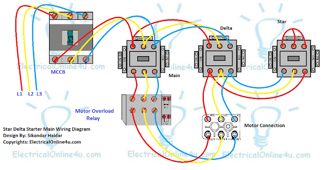
Star Delta Starter Wring For 3 Phase Motor Diagram


Star delta starter wiring diagram, this post is about the main wiring connection of three phase motor with star delta starter and control wiring diagram of star delta starter. For three phase motor we use the direct online starter but mostly for small three phase motor. But high load 3 phase motor we use the star delta starter for motor controlling. A star delta starter is type of motor starter which run 3 phase motor in star in starting time. And when the motor start, after some time it's run the motor in delta connection.

Star Delta Starter Wiring Diagram 3 Phase


To make a star delta starter you need...

1 MCCB Circuit Breaker
3 magnetic contactors
3 phase motor thermal overload relay / Electronic overload relay OCR
A on daily timer (8 pin timer with 8 pin glass type relay socket/base)
1 Normally close push button switch
1 Normally open push button switch
Electric wires for main motor wiring
Electric wires for controlling wiring

Star Delta Starter Wring For 3 Phase Motor Diagram


Here I shown the complete star delta starter wiring diagram 3 phase. The three phase supply shown with RED, Yellow And Blue Coolers.- All connection with a 3 phase induction motor.


star delta starter wiring diagram


The above is a star delta starter wiring diagram 3 phase motor for main wiring. Now let's see the star delta starter control circuit diagram with timer, NC/NO push button switches.

Star delta starter control circuit diagram


star delta starter control circuit diagram


In the above star delta starter control circuit wiring diagram with timer and normally close push button/normally open push button switch. In control wiring diagram all magnetic contactors coils are rated 220 VAC. A 8 pin timer are used. The on delay timer diagram is also shown in the diagram.

How to wire the lights in parallel:?


How to combine Lights Points in parallel?

The common domestic circuits used in electrical wiring installations are (and should be) parallel. Often, switches, outlets, receptacles, and light points, etc., are connected in parallel, if one of them fails to maintain the power supply to other electrical appliances and devices through hot and neutral wires.
In our today’s Basic Electrical Wiring Tutorial, we will show how to wire parallel lights.

How-To-Wire-Lights-in-Parallel

In the above fig, it is clearly shown that all light bulbs are connected in parallel i.e. each bulb is connected by separate line (also known as live or phase) and neutral wire.
In a parallel circuit, adding or removing one lamp from the circuit does not affect other lamps or connected devices and devices because the voltage in the parallel circuit is the same at each point but the flow current is different. In this type of circuit, any lighting point or load can only be added (according to the circuit or sub-circuit load calculation) by extending the L and N conductors to other lamps.
As each lamp or bulb is connected separately between line L and neutral N, if one light bulb is defective, the rest of the circuit will function smoothly as shown in fig below. Here, you can see that the line connected to lamp 3 has a cut in the wire, so the bulb switch is off and the rest of the circuit is working properly ie the bulb is dimming.

Faults-in-Parallel-lighting-circuits

Also, if we control each lamp through a single way (SPST = single pole single throw) in a parallel lighting circuit, we can turn on each bulb with a separate switch or if we turn off the bulb, the remaining lighting points will not be affected because it Only in the series lighting connection where all connected loads will be disconnected if we switch off.

Light-Bulbs-Connected-in-Parallel

How to control a light bulb with a single way switch in parallel lighting?

Below the fig, we controlled three light bulbs from three separate single way switches connected between the line and the neutral wire. The first two bulbs are shining because the switches are on the position while the third one is off the bulbs.

How-to-control-each-lamp-separately-by-single-way-switches-in-parallel-lighting-circuits

Advantages of Parallel Lighting Circuits:

  • Each connected electrical device and device are independent of the other. This way, turning the device on / off will not affect other devices and their operation.
  • In the case of a break in the cable or the removal of any lamp, not all circuits and connected loads will break, in other words, other lights / lamps and electrical appliances will still work smoothly.
  • If more lamps are added to the parallel lighting circuit, it will not decrease the luminosity (as it only happens in a series of electrical circuits). Because the voltage at each point in the parallel circuit is the same. In short, they get the same voltage as the source voltage.
  • Unless the circuit is overloaded, it is possible to add more light fixtures and load points to the parallel circuit as needed in the future.
  • Adding additional equipment and components will not only increase the resistance but also reduce the overall resistance of the circuit, especially when using high current rating devices such as air conditioners and electric heaters.
  • Parallel wiring is more reliable, safer and easier to use

Advantage-of-parallel-circuit-connection-over-series-connection

Disadvantages:
  • Parallel lighting wiring circuits use more size cables and wires.
  • More current is required when additional light bulbs are added to the parallel circuit.
  • Battery is fast running for DC installation.
  • Parallel wiring design is more complex than series wiring.
Information to know:
  • The switch and fuse line (live) must be connected by wire.
  • Connecting electrical devices and devices such as fans, outlets, light bulbs, etc. in parallel is the preferred method of replacing series wiring.
  • Parallel or series-parallel wiring method is more reliable than series wiring

Electrical power on the National Grid

Electrical power on the National Grid
● Electricity is generated in large modern power stations at 25 kV.
● It is then transformed up to 132 or 270 kV for transmission to other parts of the country on the National
Grid network.
● Raising the voltage to these very high values reduces the losses.
● 66 or 33 kV is used for secondary transmission lines.
● These high voltages are reduced to 11 kV at local sub-stations for distribution to end users such as fac-
tories, shops and houses at 400 and 230 V.
● The ease and effi ciency of changing the voltage levels is only possible because we generate an a.c. sup-
ply. Transformers are then used to change the voltage levels to that which is appropriate. Very high volt-
ages are for transmission, lower voltages are for safe end use. This would not be possible if a d.c. supply
was generated.
● Fig. 2.9 below shows a simplifi ed diagram of electricity distribution.